Pump affinity laws are used to estimate how a pump’s performance will change when its rotational speed is changed. They can also be applied to changes in impeller diameter, but diameter-based estimates require greater care because the relationship depends on the pump design and operating range.
The cubic power relationship is a critical operational consideration: even a small increase in pump speed can cause a significant rise in the shaft power required to drive the pump.
What Are Pump Affinity Laws?
Pump affinity laws are engineering relationships used to estimate how the performance of a centrifugal pump changes when its rotational speed or impeller diameter is changed. They help predict changes in key parameters such as flow rate, head, and power.
These relationships are most reliable when comparing the same pump at different but relatively close operating speeds, with similar fluid properties and operating conditions. They are particularly useful for understanding how a pump will respond to changes in speed rather than treating the results as exact performance values.
Pump affinity laws are commonly applied when working with variable frequency drives (VFDs), estimating shifts in pump performance curves, checking expected operating points, and evaluating motor loading.
However, the laws provide an estimate rather than a substitute for detailed pump data. Actual performance can be affected by pump design, system resistance, fluid characteristics, efficiency changes, and operating conditions. For final equipment selection or detailed hydraulic analysis, the manufacturer’s pump curve and a complete system analysis should always be considered.
Pump Affinity Laws Formulas
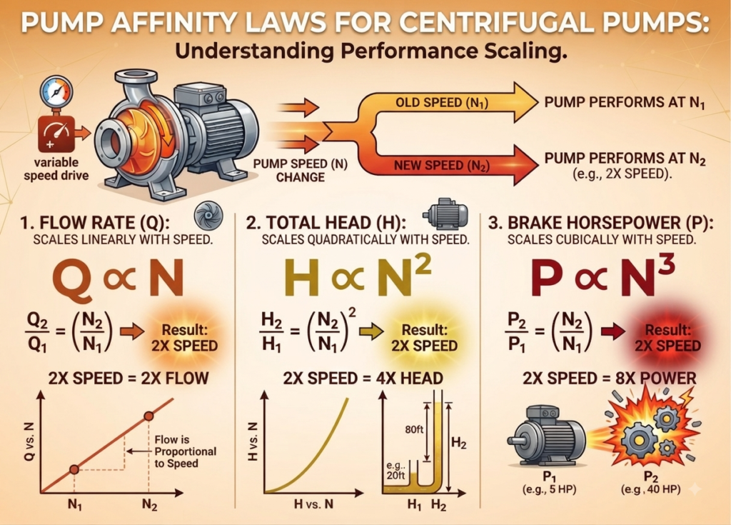
For the same centrifugal pump operating at two different rotational speeds, the pump affinity laws provide a quick way to estimate changes in flow, head, and power.
Flow Rate Relationship
The flow rate changes approximately in direct proportion to pump speed:
Where:
- (Q) = Initial flow rate
- (Q) = New flow rate
- (N1) = Initial rotational speed
- (N2) = New rotational speed
Head Relationship
Pump head changes approximately with the square of rotational speed:
Where:
- (H1) = Initial pump head
- (H2) = New pump head
Power Relationship
The required pump power changes approximately with the cube of rotational speed:
Where:
- (P1) = Initial power
- (P2) = New power requirement
Fast Interpretation
The three relationships can be remembered as:
Head → Speed²
Power → Speed³
For example, a 10% increase in pump speed means the speed ratio becomes 1.10. Under idealized affinity-law conditions:
- Flow: increases by approximately 10%
- Head: increases by approximately 21%
- Power: increases by approximately 33.1%
This cubic power relationship is particularly important during pump operation because even a modest increase in speed can produce a much larger increase in power demand.
Speed Changes With a VFD
Changing pump speed with a Variable Frequency Drive (VFD) is one of the most common applications of the pump affinity laws. When the pump geometry and fluid properties remain unchanged, the effect of a speed change can be estimated using a simple speed ratio.
Speed Ratio
First, calculate the speed ratio:
Where:
- (N1) = Initial pump speed
- (N2) = New pump speed
- (RN) = Speed ratio
The new pump performance can then be estimated using the following relationships:
Flow Rate
Flow changes directly with speed. Therefore, a 10% increase in speed will ideally produce about a 10% increase in flow.
Pump Head
Head changes with the square of speed. This means that a relatively small speed increase can produce a noticeably larger increase in pump head.
Power Requirement
Power changes with the cube of speed. This is the most important relationship to consider when increasing pump speed.
Motor Warning
Increasing pump speed can increase motor loading very quickly. Because power rises with the cube of speed, even a modest speed increase can result in a significant increase in required shaft power.
For this reason, always check the predicted shaft power against the motor’s rated capacity and confirm the operating condition using the actual pump and system curves.
For example, increasing speed by 10% gives:
Flow ≈ 10% higher
Head ≈ 21% higher
Power ≈ 33.1% higher
This is why VFD speed control should be used carefully, particularly when increasing the speed beyond the pump’s normal operating range.
Impeller-Diameter Affinity Estimates
Pump affinity relationships can also be used to make a preliminary estimate of performance changes when the impeller diameter is changed. These relationships are useful for quickly assessing the possible effect of an impeller trim.
For an initial estimate:
Flow Rate
Pump Head
Power Requirement
Where:
- (D1) = Original impeller diameter
- (D2) = New or trimmed impeller diameter
- (Q) = Flow rate
- (H) = Pump head
- (P) = Pump power
Use These Relationships as Estimates
Unlike speed-based affinity laws, impeller-diameter relationships should be treated as approximate screening tools.
Trimming an impeller changes its hydraulic geometry. As a result, the actual pump efficiency, flow-head relationship, and power requirement may not follow the ideal mathematical relationships exactly.
The difference can become more significant when the diameter reduction is large or when the pump operates away from its normal design range.
Preferred Source for Final Selection
For a pump with a trimmed impeller, the manufacturer’s performance data should always take priority.
Whenever available, use the manufacturer’s trimmed impeller performance curve to determine the actual flow, head, efficiency, and power requirements.
In practice:
Manufacturer’s trimmed curve → Final engineering reference
Pump Curve vs. System Curve
Pump affinity laws can estimate how a pump’s performance changes with speed or impeller diameter. However, they do not directly determine the actual flow rate in a piping system.
The real operating point depends on the interaction between the pump curve and the system curve.
Understanding the System Curve
The system head can be represented approximately as:
Where:
- (H) = Total system head
- (Hstatic) = Static head
- (K) = System resistance coefficient
- (Q) = Flow rate
The static head is mainly determined by the elevation difference and pressure requirements. The second term represents the head required to overcome friction and other flow-related losses.
Why Flow Does Not Simply Scale With Speed
In a friction-dominated system, increasing the flow rate also increases the system head requirement. Because friction losses are approximately proportional to the square of flow, even a moderate increase in flow can require significantly more head.
Therefore, after changing pump speed, the actual operating point is not necessarily:
This relationship represents the affinity-law scaling between corresponding pump operating conditions. It does not automatically account for the resistance of the connected piping system.
Operating-Point Check
For a more realistic estimate, first use the pump affinity laws to shift the pump curve to the new speed. Then compare the shifted pump curve with the system curve.
The point where the two curves intersect represents the new operating point.
Pump curve + System curve → Actual operating point
This approach provides a more reliable estimate of the new flow rate, pump head, and operating condition after a speed change.
For practical pump analysis, the affinity laws are therefore best used together with the system curve, rather than as a standalone calculation.
BEP, Efficiency, and Acceptable Operating Range
The Best Efficiency Point (BEP) is the region on a pump’s performance curve where the pump typically achieves its highest efficiency. Operation near the BEP is generally preferred because the pump is designed to perform smoothly and reliably around this region.
However, changing pump speed or system resistance can shift the operating point away from the BEP. The affinity-law calculations may still be mathematically correct, but the pump’s actual efficiency, vibration, and operating behavior can change.
Pump Efficiency
Do not assume that pump efficiency remains exactly the same after a significant change in speed or operating point.
A small change may have little effect, but larger changes can move the pump away from its efficient operating region. This can increase energy consumption and affect overall pump performance.
Vibration and Recirculation
Operating too far from the BEP can increase the risk of hydraulic instability, vibration, noise, and internal recirculation.
Running too far to the left or right of the pump curve can place additional stress on the pump and its components. For reliable operation, the pump should generally operate within the manufacturer’s recommended operating range.
Motor Loading
Motor loading should also be checked whenever the operating condition changes.
The cubic affinity relationship provides a useful initial estimate of how power may change with speed. However, the actual shaft power depends on the pump’s operating point and efficiency.
Therefore, after a speed change, verify the actual shaft power at the new operating point and compare it with the motor’s rated capacity.
Practical Check
For reliable pump operation, consider all three factors:
A pump should not be evaluated only by its theoretical affinity-law results. The actual pump curve, system curve, efficiency, operating range, vibration, and motor capacity should also be checked.
NPSH and Cavitation Checks After a Speed Change
Changing pump speed can affect more than just flow, head, and power. An increase in speed can also increase the risk of cavitation, particularly when the suction conditions are already close to their limits.
Understanding NPSH
Net Positive Suction Head (NPSH) is an important parameter used to evaluate whether a pump has sufficient suction pressure to operate safely without excessive vapor formation.
Two values are commonly considered:
- NPSH Available (NPSHₐ): The amount of suction head actually available from the system.
- NPSH Required (NPSHᵣ): The minimum suction head required by the pump for the specified operating condition.
For reliable operation:
An adequate safety margin should also be maintained according to the pump manufacturer’s recommendations and applicable engineering practice.
What Happens When Speed Increases?
Increasing pump speed generally increases flow and can increase the pump’s NPSH required. However, the system’s NPSH available may not increase with the pump speed and can sometimes decrease because of higher suction-line losses.
This means that a speed increase that appears acceptable from the affinity-law calculations may still create a suction-side problem.
Cavitation Warning
Never approve a higher pump speed based on affinity laws alone.
After changing speed, check the NPSH available against the manufacturer’s NPSH required value at the new operating point.
A proper speed-change assessment should therefore consider:
This additional check helps prevent cavitation, vibration, noise, reduced pump performance, and premature damage to the impeller and other pump components.
Worked Example
Example 1: Estimating Pump Performance After a Speed Increase
A centrifugal pump operates at 1450 rpm, delivering 420 gpm against a head of 65 ft and consuming 14 hp. Estimate the approximate flow rate, head, and power when the pump speed is increased to 1740 rpm.
Using the pump affinity laws:
Flow rate:
Head:
Power:
Key point: A 20% increase in pump speed increases flow by approximately 20%, head by 44%, and power by about 73%. This illustrates why motor loading and NPSH should be checked before increasing pump speed.
Example 2: Impeller Trim Estimate
A centrifugal pump is fitted with a 12 in impeller and operates at 1,050 gpm, producing 135 ft of head while requiring 48 hp. Estimate the idealized performance after trimming the impeller to 10.8 in.
Using the affinity relationships for an impeller diameter change:
Flow rate:
Head:
Power:
These values are ideal first-pass estimates based on the affinity relationships. Actual performance after impeller trimming can differ because of pump geometry, hydraulic efficiency, and operating conditions. Final selection should always be verified against the manufacturer’s trimmed-impeller performance curve.
Example 3: Finding Pump Speed for a Target Flow
A centrifugal pump currently delivers 350 gpm at 1500 rpm. Estimate the pump speed required to achieve a target flow of 420 gpm.
Using the affinity law for flow:
Therefore,
So, the estimated speed required to obtain 420 gpm is 1800 rpm.
The corresponding ideal head multiplier is:
The ideal power multiplier is:
Interpretation: A 20% increase in flow requires approximately a 20% increase in speed under ideal affinity-law scaling. However, the corresponding head increases by about 44%, while power increases by approximately 73%.
Therefore, before increasing the pump speed, verify the motor capacity, pump operating range, NPSH, vibration, and manufacturer’s pump curve.
Assumptions and Limitations
The pump affinity laws are useful for preliminary estimates, but their application depends on several conditions. Before using them, consider the following:
- Centrifugal pump application
The relationships are primarily intended for centrifugal pumps operating under comparable conditions. - Similar fluid conditions
The fluid should have broadly similar density and viscosity. Significant changes in fluid properties can affect actual pump performance. - Comparable operating region
The pump should remain within a suitable portion of its performance curve. Extrapolating too far from the original operating point can produce unreliable results. - Efficiency must be verified
Affinity-law calculations do not guarantee constant efficiency. Actual efficiency can change after a speed or impeller-diameter adjustment and should be obtained from the manufacturer’s data. - System and equipment constraints
A preliminary affinity-law estimate is not a final design check. The system curve, BEP, NPSH available versus required, motor loading, and allowable operating limits must be evaluated separately.
In short: affinity laws are excellent for first-pass estimation, but final pump selection or modification should always be confirmed using the actual pump and system curves.
When the Simple Affinity Model Is Not Enough
Pump affinity laws are valuable for preliminary calculations, but they should be applied carefully when operating conditions change significantly. Extra caution is required in the following situations:
- Large speed changes: Significant speed increases or reductions can move the pump far from its original operating condition.
- Cavitation-sensitive operation: A speed increase may raise NPSH requirements and reduce the available safety margin.
- High-viscosity fluids: Viscous liquids can cause substantial changes in flow, head, and efficiency compared with water-based assumptions.
- Non-standard impeller trimming: Actual trimmed-impeller performance may differ from simple diameter scaling.
- Dissimilar pump designs: Affinity relationships should not be blindly transferred between pumps with different hydraulic designs or geometries.
- Operation near curve limits: Results become less dependable when the pump operates close to shutoff, runout, or other extreme regions of its characteristic curve.
Common Mistakes and Engineering Checks
The affinity laws should be treated as an engineering estimation tool, not as a substitute for the complete pump and system analysis. Common errors include:
- Skipping the system curve
Calculating a new pump point from affinity laws alone does not establish the actual operating point. The modified pump curve must intersect with the system curve. - Underestimating power demand
Because power varies approximately with the cube of speed, even a moderate speed increase can cause a substantial rise in power and motor loading. - Assuming constant efficiency
Pump efficiency can change as the operating point moves. A calculated power value should therefore be treated as an estimate unless supported by actual pump data. - Treating impeller scaling as exact
Diameter-based affinity relationships provide an approximation. Manufacturer-supplied trimmed-impeller curves are more reliable for final evaluation. - Ignoring BEP and operating limits
The new operating point should be checked against the Best Efficiency Point (BEP) and the pump manufacturer’s recommended operating range. - Overlooking NPSH requirements
Any increase in speed should trigger an NPSH check, because inadequate NPSH margin can lead to cavitation, noise, vibration, and pump damage.
Conclusion
Pump affinity laws provide a practical method for estimating how flow, head, and power may change when pump speed or impeller diameter is modified. They are especially useful for preliminary engineering calculations, troubleshooting, performance evaluation, and assessing potential pump modifications.
However, affinity-law calculations should be considered first-pass estimates rather than exact predictions. Actual pump performance can be influenced by the system curve, pump efficiency, fluid properties, BEP, NPSH requirements, motor capacity, and the manufacturer’s recommended operating range.
For reliable engineering decisions, the calculated result should always be compared with the manufacturer’s pump performance curve and the actual system curve. Particular attention should be given to motor loading, cavitation risk, efficiency, and operation within the acceptable pump range.
In practice, affinity laws are most valuable when used as a quick engineering tool, followed by detailed verification before implementing a speed change or impeller modification.
Read Next:
- Centrifugal Compressor Efficiency: Formula, Factors, Improvement
- Compressed Air Leak Detection
- Air Compressor Energy Saving: 23 Proven Ways to Reduce Compressed Air Energy Costs
- Specific Power: Formula, Units, Importance & Examples
- Specific Energy Consumption (SEC): Formula, Unit, Calculation, and Examples